Multi-functional Object Avoidance Robot (code-name WALL-E)
First of all, it's name is WALL-E just cuz I liked Disney's movie of WALL-E. And now to the point, this project was started when I was in 9th Grade at CIRS, Coimbatore with Pratham Mehta. Originally, it was designed just to be a simple remote controlled toy to experiment on some human joint functions (like the arms and neck) but then later on, we expanded the project to make it controllable using a computer. This was achieved using L293D IC chips connected to an old laptop's parallel port. The L293D is a Motor Driver Integrated Circuit which can be used to alter speed and direction of a motor using 2 parallel port outputs. With 16 parallel port output ports in a socket, you can only control 4 motors. Therefore, later we planned to use the 89V51RD2 IC which let's us use a wireless router to communicate with the PC. We've got a lot of information on using the 89V51RD2 from a Final Year Computer Science Engineering Project at SARVAJANIK COLLEGE OF ENGINEERING & TECHNOLOGY. Their project report is available here. Later, we also experimented with PIC16F628A for using serial/USB ports to communicate.
After we managed to get basic communication (at this time, using the L293Ds and parallel port output to test) with the robot, we went into programming it using Visual Basic IDE and QuickBASIC. Note that InpOut32.dll must be installed to be able to communicate using the parallel port. The obstacle avoidance part used at first TSOP sensors to look for obstacles and sends data through the parallel port's INPUT lines (there're 5 input lines in a parallel port). This is then received by the computer and the Programs created to control it tell it what to do. The First Visual Basic Application made for parallel port control is available here. You can get the pseudo-code (I kinda lost the actual Visual Basic Code, but I remember how it worked) here.
Something else done for fun to this project is a 3D (anaglyphed view) of what it sees. The robot can also be controlled manually, and 2 web-cams fitted on it about 8 centimeters apart stream 2 different video files, 1 tinted in Red and the other tinted in Cyan. These 2 form a 3D anaglyph which can be viewed using the Simple Red-Cyan 3D glasses. This not only lets us see what it sees but also let's us predict the distance to an obstacle.
I've also looked into NOIR face-tracker but nothing related to that has been implemented in this project. We're thinking of converting the face position co-ordinates into commands for the motors for our next robot project. But I've decided to use servo's for the next one, so even better.
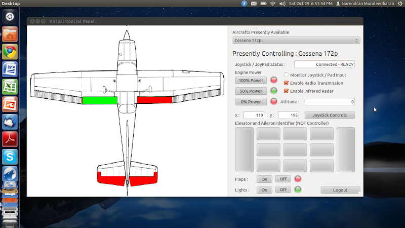
Computer Controlled R/C Plane and PID Autopilot
After moving to Linux/Ubuntu, I've been experimenting with a few Programming IDEs and found a really nice program, very similar to Visual Basic called GAMBAS. To experiment with GAMBAS, I created another parallel port output application that ALSO connects to a joystick using USB serial input. So well basically, it's an app that connects USB to parallel output. And then, I found out about VEX-RC 6 channel remote control transmitter and receiver kit which is a simple alternative to using the 89V51RD2 IC and a wireless router! By opening the transmitter and connected the parallel port output pins to it, you can transmit 6 channels across. I gave 2 channels each for the ailerons, elevators and rudder. As much as the program was built, it didn't yet transmit anything to the R/C plane yet because I didn't get the VEX-RC kit. I focused on the software and completed that part though. The GAMBAS Project Source is available for download here. And later, I looked into how FlightGear's, a FOSS (Free and Open Source) Flight Simulator Autopilot System works and used their PID (Proportional Integral Derivative) Auto Pilot Controller to work on an autopilot for this. It requires a gyro-scope, an altimeter and a compass to get inputs and sends output to the 6 control channels. The PID Controller I wrote is available here.
3D Aircraft Models in Ac3D.
On December 2009, My father took me to a CAD (Computer Aided Design) class where I learnt basic 3D designing with SolidWorks. I learnt a lot there and then decided to try modeling on my own. Unfortunately, SolidWorks was quite expensive so I got Ac3D, another neat modeling program. I was (and still am, actually) quite interested in aircraft and aerodynamics so I tested my skills by modeling a few aircraft from blueprints I got over the internet. It just took me about 2 to 3 days for each of the models so I made 4 altogether. You can download the models I made by clicking on the links: Airbus A330-200, Embraer ERJ170-100, Avro Regional Jet RJ100, BWB-450 (NASA's Blended Wing Body Concept). First, I get some layouts/blueprints from Google Images and then use Ac3D's modeling tools to create a wire-frame. Then I create textures with GIMP (GNU Image Manipulation Program) and Texture Map it with Ac3D's texture co-ordinate editor. I've also worked on a JSBSim (output of DATCOM+) Flight Dynamic Model for the BWB-450 but I was never able to finish it.
Anyway, you can open the above models with Ac3D itself or Blender (a FOSS Modeling program) or you could just take a look at the screen-shots I took from my modeling program.
Magnetic Levitation Train (Design and Plans ONLY)
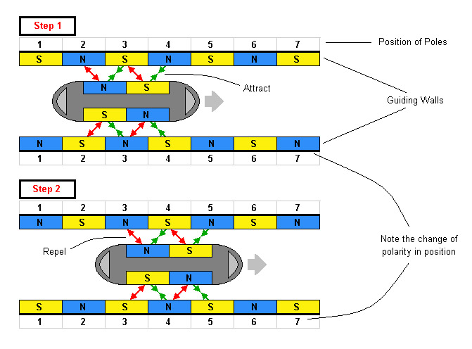
A MagLev (short for Magnetic Levitation) Train is a method of rail transport which uses the attractive and repulsive forces of magnets/electromagnets. The greatest advantage of levitating trains is that there's no friction in the air, and the air-resistance is very minimal, a good aerodynamic shape should take care of that. Currently, MagLevs use support magnets on the under-carriage for levitation and guidance magnets along the side to move. For guidance, the signs of the magnetic fields on track changes. A set of charges move along with the train and thus attracting the train forward.
We wanted to originally make this but then this would be a huge waste of resources on the track. Therefore, we worked on something (oh and btw, we means Pratham and I) that makes the sign of the magnet on the train change instead of the whole track. We could use a sensor to find out the field and give that input to the processor. (which could be a combination of an inverter and sensor transistor circuit or a programmed Arduino micro-processor) I prefer the Arduino because we could also program outputs to slow down, stop or speed up the train too. But anyway, the track has magnets with each sign periodically. (look at the figure) Then, there're slits on the tracks which start about halfway after a certain sign and end a bit after halfway through the next sign. So, when the IR module senses the slit, the magnetic field on the electromagnet aboard the train reverses. So, when the EM end just passes over the center of a North pole, that end becomes the North Pole of the EM. Then, it repels most of the NP of the track magnet and attracts the SP on the track. After the slit is over, the charge returns and then the front end becomes the South Pole thus repelling the South Pole it's over and attracting the North Pole coming up. This repeats throughout the track. The IR module and the slits are just to make it easier for us to build. We could also just use the magnet on the track to induce current in a wire and use a Galvanometer to find the direction of the current and use that output for changing the EM poles.
We had planned this project for Intel Science and Engineering Fair 2011 but we went to different schools for our 11th and 12th grades in 2 different cities and thus wasn't able to build this. We're still planning to do it after our 12th Grade. But anyway, here's a slideshow of our stuff. We also have an 'ac3d' model we made which is incomplete but available here.
I'll probably update this if/when we're done with testing and building it. :)
Windows Folder Lock Application (Batch File converted to Executable)
Nothing much here, just a simple folder lock and guard application I made for Windows Operating Systems. It's not very fancy as folder guard or CyberLock but it works just fine.
It was made by writing a batch file and converting it to an executable with a free batch-to-exe converter. You can lock folders with this application and only reveal it again when you enter your password.
You can download the application here, the source batch files and the batch-to-executable converter are included.
My C++ Console Applications
I've taken C++ for my 11th grade and learnt a lot there. I decided to explore some more by creating new applications with it. I made a whole bunch of Standard (not the old Borland one) C++ applications that do all kinds of things like calculate teh quadratic roots, find the area of a triangle, write the fibonacci sequence etc. They were all made either on gedit, a simple text editor for linux or Code::Blocks IDE, an awesome C++ console application IDE for linux. The whole folder of the codes and workspaces is compressed and avaialble here. The download includes both the programs (executables) and the c++ files. I've used gcc to compile the c++ files so they may not work on windows. But it's very easy to compile the cpp files so that they do.